3800 Series 2 Engine Diagram Youtube with 3800 Series 2 Engine Diagram image size 480 X 360 px and to view image details please click the image. Basics 9 416 kV Pump Schematic.
2004 Ford Explorer 40 Serpentine Belt Diagram Wiring Site Resource
These diagrams are current at the time of publication check the wiring diagram supplied with the motor.

Printable 5 4 belt diagram and the description. Basics 8 AOV Elementary. Identify and define the different symbols used in ladder diagrams. Print Mechanism Components Item Number Description Part Number Quantity.
Basics 3 416 kV Bus 1-Line. A belt conveyor system is one of many types of conveyor systemsA belt conveyor system consists of two or more pulleys sometimes referred to as drums with a closed loop of carrying mediumthe conveyor beltthat rotates about them. This human anatomy module is composed of diagrams illustrations and 3D views of the back cervical thoracic and lumbar spinal areas as well as the various vertebrae.
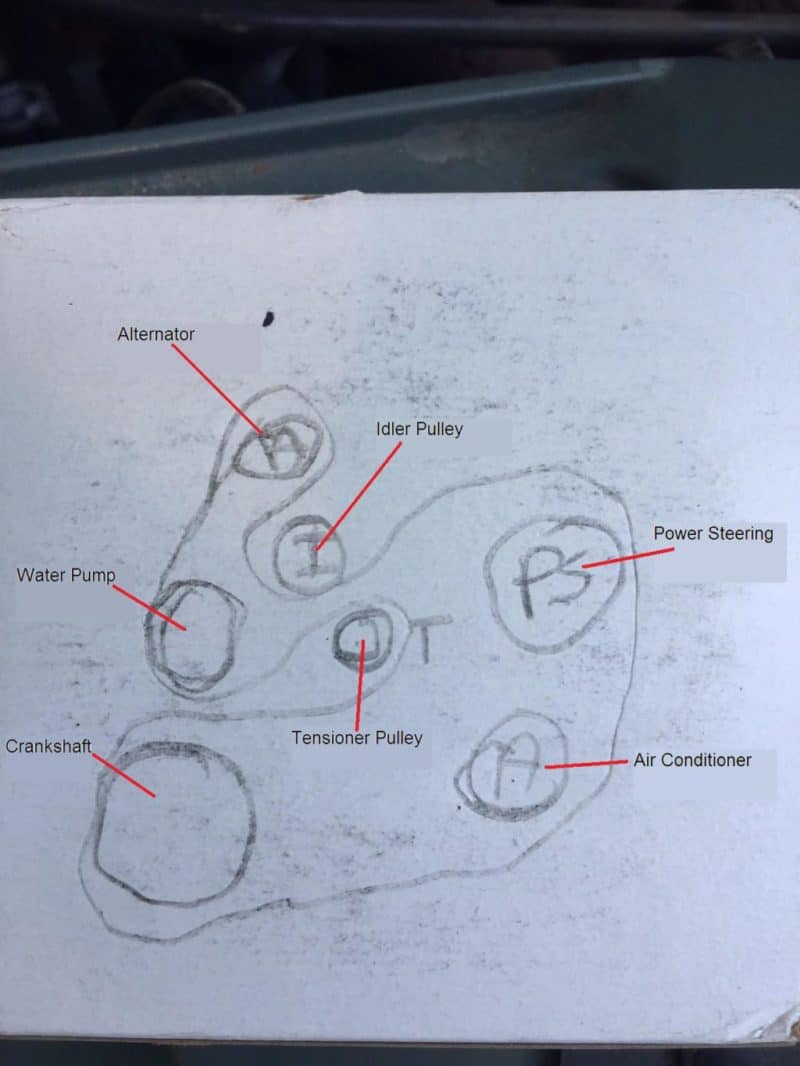
How to Make a Family Tree Template. The belt should be long enough to route around all of the pulleys except the tensioner until you relieve the pressure on it. WIRING DIAGRAMS Diagram ER9 M 3 1 5 9 3 7 11 Low Speed High Speed U1 V1 W1 W2 U2 V2 TK TK Thermal Overloads TWO SPEED STARDELTA MOTOR Switch M 3 0-10V 20V 415V AC 4-20mA Outp uts Diagram IC2 M 1 240V AC 0-10V Outp ut Diagram IC3 M 1 0-10V 4-20mA 240V AC Outp uts These diagrams are current at the time of publication.
In the case of an ancestor tree your namethe name of the person making the family tree should be at the bottomor left and the name of the parents grandparents and maybe great-grandparents should expand upwards or towards the right. 20112015 Run the new belt through the pulleys in exactly the same way the old one was. Use keywords or part numbers instead of full sentences for best results.
The internal system diagram of the igniter is shown below. Wiring_5qxd 20112015 1137 AM Page 9 Created Date. K040310RPM K04 916 x 31 58 - Black 4 3113 791 31625 803 K040315RPM K04 916 x 32 14 - Black 4 3165 804 3225 818.
A characteristic of this igniter is that it contains the 3 power. A conveyor belt is the carrying medium of a belt conveyor system often shortened to belt conveyor. Convert the given function block diagram to ladder diagram.
Symbol Description Symbol Description Symbol Description Safety alert See Owners Manual Anti-lock braking system Avoid smoking flames or sparks Battery Battery acid Brake fluid non petroleum base Brake system Cabin air filter Check fuel cap Child Safety Door Lock and Unlock Child seat lower anchor Child seat tether anchor Cruise. Timing Pulleys and Belt The timing belt tooth configuration has been. It is particularly interesting for physiotherapists.
One or both of the pulleys are powered moving the belt. Symbols 4-4 57 4 C100 329 PK Other circuits which share fuse 18 but are not shown can be referenced in Power Distribution A choice bracket shows wiring differ-ences between mod-els countries or op-tions Circuit number Connector reference number for component location chart Wire insulation is one color Pin number 4 C103 329 PK Two connections. BELT DIMENSION CHART.
Draw the truth table and write the output boolean expression for the given ladder diagram. Basics 6 72 kV 3-Line Diagram. Refer to the belt diagram in your vehicles owners manual or the picture you took of the belt before removing it to guide you.
FHT Timing Belts Miniature Drive System The FHT Fenner High Torque curvilinear timing belt system provides smooth operation and high torque carrying capacity with low backlash. These mini-pitch synchronous timing belts and pulleys are available in the following pitches. 300 dpi P1006072 1 5 Rewind Drive System includes pulleys and drive belts for all dpi 105SLPlus.
RPM Belt Length Speed Animated Diagrams. 737-3025 1234 filter oil pump etc. Basics 7 416 kV 3-Line Diagram.
For example if your small pulley is 80mm diameter and spins at 1000 RPM and you need to find the second pulley size to spin it at. Description The 5VZFE engine newly developed to replace the 3VZE engine is a V6 34liter 24valve DOHC engine based. Basics 4 600 V 1-Line.
Basics 10 480 V Pump Schematic. Basics 11 MOV Schematic with Block included Basics 12 12-208 VAC Panel Diagram. Number Description Part Number Quantity.
Part Number Product Description Number of Ribs Effective Length in Effective Length mm Outside Circumference in. SmartDraw Templates and Examples. Identify the ladder diagram elements.
If you know any 3 values Pulley sizes or RPM and need to calculate the 4th enter the 3 known values and hit Calculate to find the missing value. We hope this article can help in finding the. 4 Rewind Drive Belt for 105SLPlus 203.
KIRBY Vacuum Genuine Parts Schematic Parts for Kirby ModelsGeneration 3 G4 G5 G6 Ultimate G Diamond Edition Sentria Not all parts are available some parts may be out of stock or discontinued Kirby Vacuum Schematic Diagram Section 1 Kirby Vacuum Base and Handle Parts KeY Part no. Here is a picture gallery about 3800 series 2 engine diagram complete with the description of the image please find the image you need. Draw ladder diagrams for simple logic operations.
22092020 Anatomical diagrams of the spine and back. DeSCriPtion KeY Part no. It contains the osteology arthrology and myology of the spine and back.
Basics 5 480 V MCC 1-Line. 4 Generation Pedigree Chart.
Diagram 2005 57 Hemi Belt Diagram Full Version Hd Quality Belt Diagram Diagraman Assimss It
Diagram 1996 5 4 Engine Diagram Full Version Hd Quality Engine Diagram Diagraminfo Ladolcevalle It
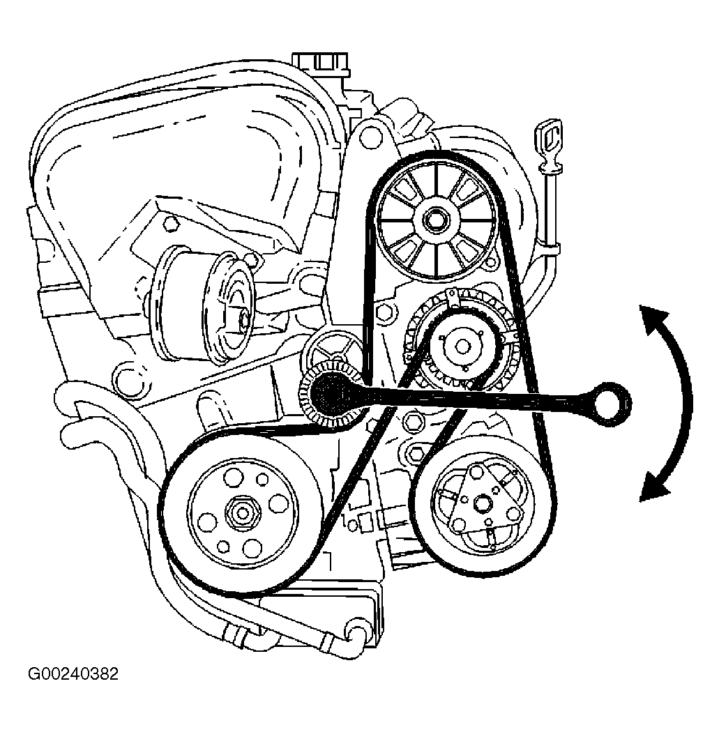
 Diagram 07 Volvo S40 Belt Diagram Full Version Hd Quality Belt Diagram Paindiagram Premioraffaello It
 3 2 T6 Serpentine Belt Diagram
 2004 Ford Explorer 40 Serpentine Belt Diagram Wiring Site Resource
 Diagram 1997 F150 Belt Diagram Full Version Hd Quality Belt Diagram Jdiagram Fimaanapoli It
 Diagram Yaris Belt Diagram Full Version Hd Quality Belt Diagram Diagraminfo Ladolcevalle It
 Diagram 1998 Ford F 150 Serpentine Belt Diagram Full Version Hd Quality Belt Diagram Waldiagramacao Lavocedelmarefilm It


