Level and work down. Pushing input potentiometer to the right past the summing junction.
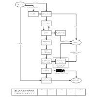 Block Diagram Learn About Block Diagrams See Examples
The input envelope is then used to modify the input the input is divided by its envelope giving the companded always large input which is passed to the upper ADC.
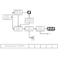
Original block diagram and the description. NiseControl Systems Engineering 3e. Each block describes a specific process within the system in terms of a transfer function. Consists of amplifiers filters mixers oscillators demodulators transducers.
It consists of individual transducers sensors for measurement of physical plant Parameters such as temperature pressure flow etc. Types and Uses of Block Diagrams. Mechatronic systems in.
Its structure provides a high-level overview of major system components key process participants and important working relationships. A block diagram is a specialized high-level flowchart used in engineering. It is used to design new systems or to describe and improve existing ones.
Block diagram of a hypothetical simple CPU showing instruction fetch decode data registers ALU and memory interface and major relationships. Figure 535 Block diagram reduction for the antenna azimuth position control system. Block Diagram RepresentationBlock Diagram Representation The convolution sum description of an LTI discrete-time system can in principle be used to implement the system.
Final closed-loop transfer function 2000 John Wiley. Figure 5 a 3. Dimensionally transfer functions can be ratios of interdisciplinary quantities.
What is a Block Diagram. Showing equivalent forward transfer function. A block diagram is an essential method used to develop and describe hardware or software systems as well as represent their workflows and processes.
The internal block diagram is used to describe the structure of a block in terms of how its parts are interconnected. The receiver consists of the same sequence of block diagrams. Block diagrams are a generalized representation of a concept and are not intended to display complete information in regards to design or manufacture.
The input is passed to the prototype non-companded DSP digital envelope detection is done on its states ratios of envelopes are computed. Original PowerPoint slides prepared by S. The block definition diagram is used to define blocks and the relationships between them such as their hierarchical relationship.
Block Diagram consists of Blocks and Lines. A block diagram is a direct graphical illustration of a set of coupled linear differential equations2. Whatever was done in the transmitter will be undone in the receiver.
It can also be used to specify instances of blocks including their configurations and data values. 12092018 Block diagram of a PC computer based data acquisition is shown in figure. Unlike schematics blueprints and layout diagrams block diagrams do not portray the necessary detail for physical construction.
Block diagrams are used in electronics to represent systems and their shifting eg. 10022018 A block diagram of a system is a pictorial representation of the functions performed by each component and of the flow of signals. From concept to detail stopping short of the actual schematic The clearer the block diagram.
Such a diagram depicts the interrelationship that exists among the various components. Block diagrams are made simple so as not to cloud concepts. 28072019 Recovers the original signal in spite of the noise.
Blocks are defined as functions AD CPU etc Lines are defined as Signal Pathways Rx data Serial data 60dB amplified signal etc Your Block diagram should start at a higher.
 Block Diagrams An Overview Sciencedirect Topics
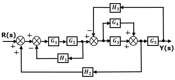 Control Systems Block Diagram Reduction Tutorialspoint
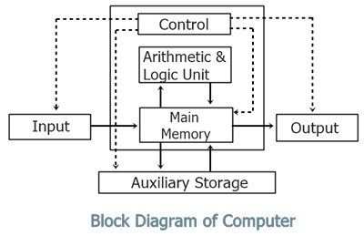 Block Diagram Of Computer With Description
 Chipset Block Diagram Information Technology Technology System
 Image 4 Jpg 415 316 Block Diagram Control Unit Coding
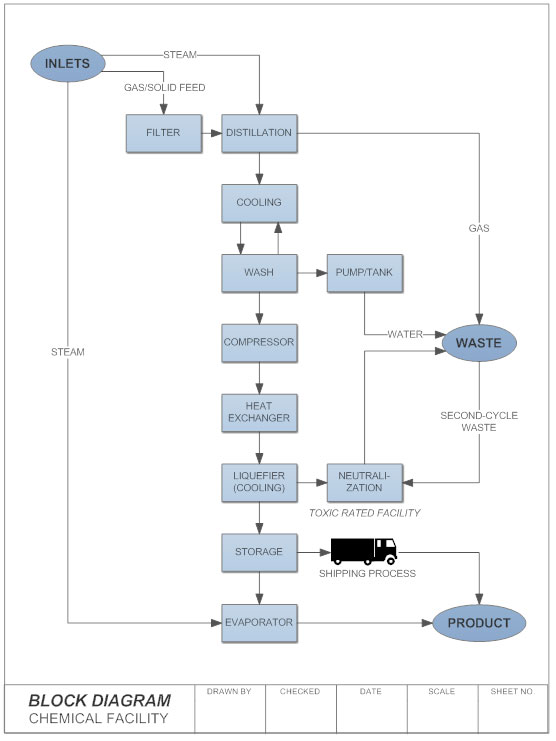 Block Diagram Learn About Block Diagrams See Examples
 Block Diagram Learn About Block Diagrams See Examples
 Block Diagrams An Overview Sciencedirect Topics


