DFDs only show essential. Data Flow Diagram DFD provides a visual representation of the flow of information ie.
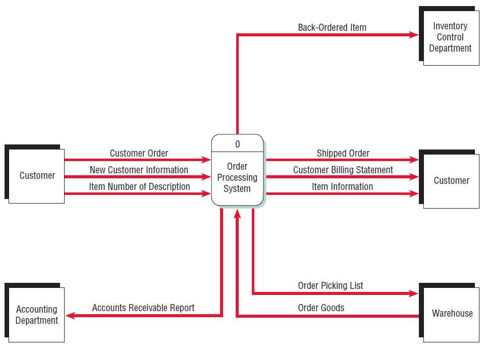 A Data Flow Diagram Dfd Example
Steps eg steps that do not process.

Original data flow diagram example and the description. The diagrams shown in this unit were developed using SELECT SSADM Professional version 411. Coads Object Oriented Analysis and Design OOAOOD was a way of visualizing software systems before UML diagrams. Specific operations based on the data can be represented by a flowchart.
Data Flow Diagramming Rules Data flows data flows are unidirectional a data flow may fork delivering exactly the same data to two different destinations two data flows may join to form one only if the original two are exactly the same no recursive data flows data flows and data stores and sourcessinks are. Level 1 Data Flow Diagrams Level 1 DFD decomposes each parent process of the Level 0 DFD into more details. As you see the above Clothes Order System Data Flow Diagram Example shows three processes four external entities and also two data stores.
Verify availability of course Enroll student and confirm registration. It is used as the part of system documentation file. Here is our level 1 data flow example a decomposition of the Clothes Ordering System illustrated in the context DFD.
At times DFD can confuse the programmers regarding the system. Data flow diagrams became popular in the 1970s in software development. Flow chart diagrams can be useful for describing programming logic or understanding a single sequence of process activities.
Data within a system. By creating a Data Flow Diagram you can tell the information provided by and delivered to someone who takes part in system processes the information needed in order to complete. An example of numbering for a process is 11.
These diagrams specify the software hardware files and people involved in an information flow. You can edit this Data Flow Diagram using Creately diagramming tool and include in your reportpresentationwebsite. 04062020 An example of the first level of numbering for a process is 1.
Data Flow Diagrams are usually produced using a CASE tool although they can be produced simply with a pencil and paper. Similarly only one entity exists as a student. Using a CASE tool for construction of the DFDs has many advantages.
A data-flow diagram has no control flow there are no decision rules and no loops. A detailed physical data flow diagram can facilitate the development of the code needed to implement a data system. Customer_info LastName FirstName SS Tel etc Order_info OrderId Item OrderDate CustomerID etc.
12032021 Data Flow Diagram Symbols DFD symbols are consistent notations that depict a system or a process. Data Flow Diagrams can be understood by both technical or nontechnical person because they are very easy to understand. Process and so this is not included on the context diagramData Flow Diagrams Context Diagram GuidelinesFirstly draw and name a single process box that represents the entire system.
30032013 Whilst a book supplier would communicate with various agencies for example publishers and other suppliers - these data flow are remote from the apossystemapos. A Data Flow Diagram DFD Example. The DFD also provides information about the outputs and inputs of each entity and the process itself.
There are two database tables courses and student info. 16022015 Data Flow Diagram with Examples - Customer Service System. It is not just a drawing tool.
It entails the use of short-text labels arrows circles and rectangles to describe data flow direction. Flow charts often show both processing steps and data transfer. A data-flow may represent a single data element such the Customer ID or it can represent a set of data element or a data structure.
Download the above diagram in PDF. A data flow diagram DFD maps out the flow of information for any process or system. A process must receive at least one data flow coming into the process and create at least one data flow leaving from the process.
A Data Flow Diagram showing Description of existing system. A data store should be connected to at least one process. It also contains data stores external entities and data flows.
A data flow diagram has four basic elements. A data-flow diagram is a way of representing a flow of data through a process or a system. They were first described in a classic text about Structured Design written by Larry Constantine and Ed Yourdon.
DFD symbols data flow diagram Example of Data Flow Diagram DFD In this example there are three processes. It uses defined symbols like rectangles circles and arrows plus short text labels to show data inputs outputs storage points and the routes between each destination. It is important to recognize however that DFDs are not flow charts.
There are several notations for displaying data-flow diagrams. Physical data flow diagrams focus on how things happen in an information flow. The data flow diagram must have at least one process and must not have any freestanding objects or objects connected to themselves.
Also forming part of DFDs are varied sub-processes data storage points and data inputs and outputs. This example called Worlds Trend Catalog Division will also be used to illustrate concepts covered in Chapters 8 and 9. 01052020 Data Flow Diagram represent detailed and well explained diagram of system components.
The following example is intended to illustrate the development of a data flow diagram by selectively looking at each of the components explored earlier in this chapter.
 Pin On Data Flow Diagram Examples
 Data Flow Diagram Templates To Map Data Flows Creately Blog Data Flow Diagram Flow Diagram Example Flow Chart Template
 Pin On Data Flow Diagrams Yc Examples
 Data Flow Diagram An Overview Sciencedirect Topics
 Data Flow Diagram An Overview Sciencedirect Topics
 Data Flow Diagram An Overview Sciencedirect Topics
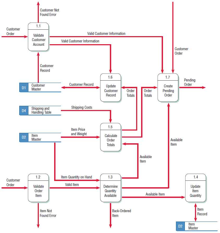 A Data Flow Diagram Dfd Example
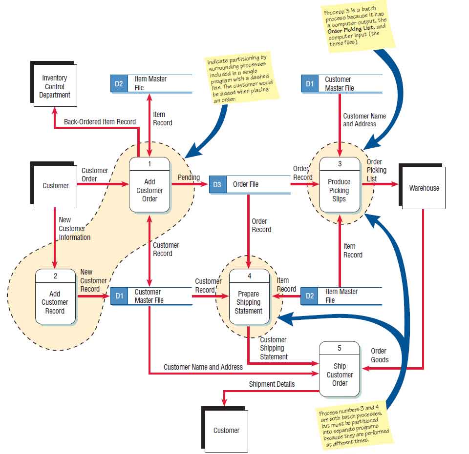 A Data Flow Diagram Dfd Example
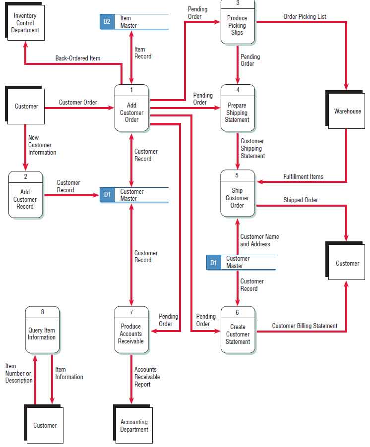 A Data Flow Diagram Dfd Example
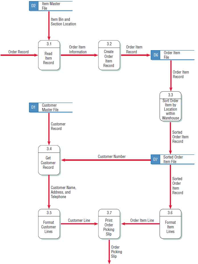 A Data Flow Diagram Dfd Example
 Data Flow Diagram An Overview Sciencedirect Topics

