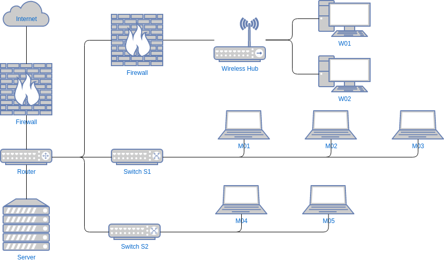
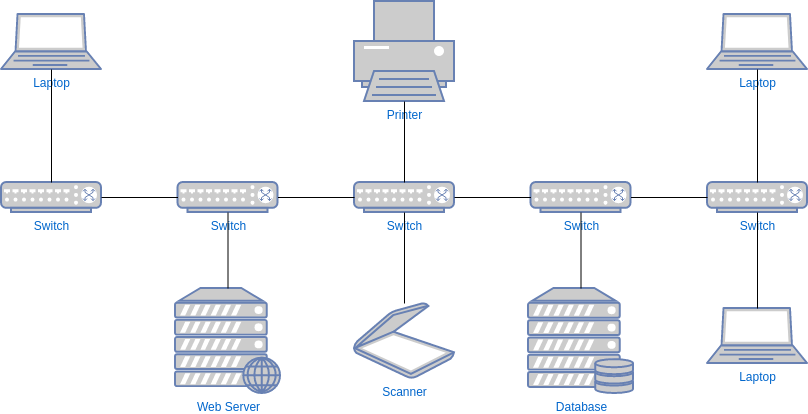
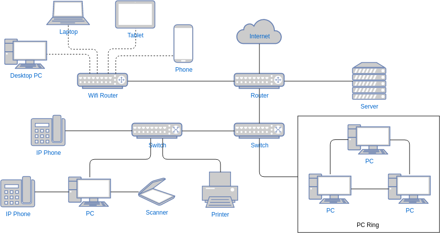
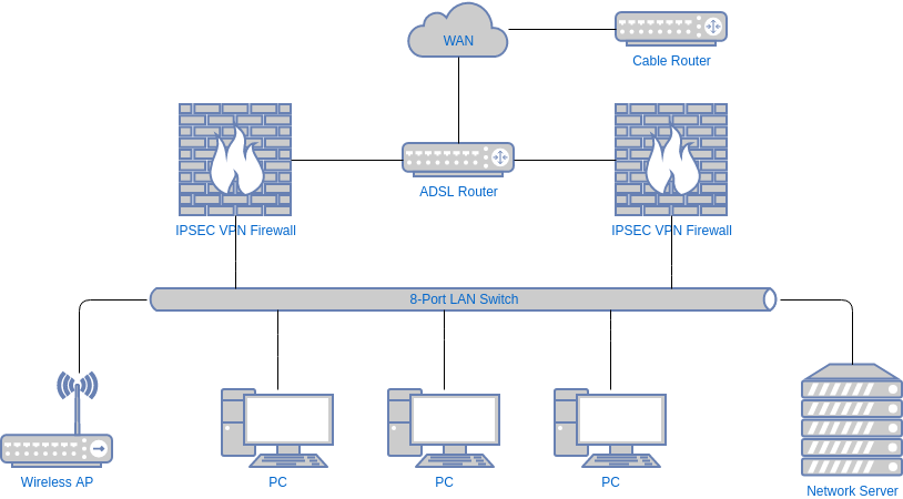
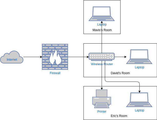
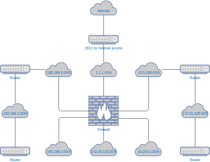
A logical network diagram depicts how information in the network flows. 25042021 In the Sequence Activities process of Project Time Management the major output is a Network DiagramBut what is a Network Diagram.
 Pin On Architecture Design Patterns
Network diagrams are divided into Physical Network Diagrams and Logical Network Diagrams.

Original logical network diagram and the description. 05092018 Logical Network Diagrams Explained. They use a combination of nodes and arrows to pictorially depict activities and relationships among those activities. In a logical diagram youll generally visualize the following elements in your logical network topology.
Network diagram is the tool for description study and analysis of network knots and connections between these knots. VHDL into a set of logic expressions that describe the logic functions Often the. It is not concerned with how the system will be constructed.
Common network diagram symbols and icons. Instead it describes the business events that take place and the data required and produced by each event. Used to organize the description of the architecture of a software-intensive system.
Within the OSI model of networking logical diagrams are referred to as L2. A logical network diagram is an illustration of the networked architecture for a group of interconnected computers or other devices. How Logical Network Diagrams.
Network diagrams can show everything from high-level networks such as connectivity across cities to more granular networks such as an office buildings network. Created network diagram can present you the existing information in comprehensible graphic view. 20092015 A logical network is a virtual representation of a network that appears to the user as an entirely separate and self-contained network even though it might physically be only a portion of a larger network or a local area network.
23042020 The logical network Diagram will be used to represent how you network connections are using the upper layer of the OSI and will help to understand your IP addressing. It involves compiling or translating the design entry eg. In the online PMP training its purpose is explained as visualizing the project activities in boxes with the activity IDs and showing the interrelationship of activities with arrowsNetwork diagrams tell if an activity will start before.
A logical data flow diagram focuses on the business and how the business operates. The information in a logical network diagram contains details that tell users how domain names are assigned which servers perform specific tasks and how all network components communicate with each other frequently taking into consideration. Since they are used for developing project management schedule they are also called Project Schedule Network Diagrams and Logical Network Diagrams.
15092004 The activity diagram must be consistent with the behavior from the corresponding logical and node logical activity diagrams in Figure 1724 and Figure 1730 respectively and also realize the original behavior specified for the monitor intruder action in Figure 1715 including its inputs outputs and any pre- and post-conditions. Therefore logical network diagrams typically show subnets including VLAN IDs masks and addresses network devices like routers and firewalls and routing protocols. 05062014 Project management network diagrams are used for schedule preparation and analysis.
More Related Network Diagram Software. Synthesis process of generating a logic circuit from an initial specification given in schematic diagram or HDL. Data flow diagrams are categorized as either logical or physical.
Since there are hundreds of possible. The major functionality and perfor- mance requirements of the system as well as other nonfunctional require- ments such as reliability scalability portability and system availability. IP addresses VLAN IDs and subnet masks network objects routers and firewalls specific routing protocols.
30082018 Logical network diagrams focus in on how traffic flows across the network IP addresses admin domains how domains are routed control points and so on. Logical topologies are bound to the network protocols that direct how the data moves across a network. 20012021 A logistics network diagram example combines network graphics and data to present logistics network diagrams architectures business process flows.
Network diagrams are useful for mapping the connections in a computer or telecommunications network. It might also be an entity that has been created out of multiple separate networks and made to appear as a single network. Logical network diagrams A logical network diagram describes the way information flows through a network.
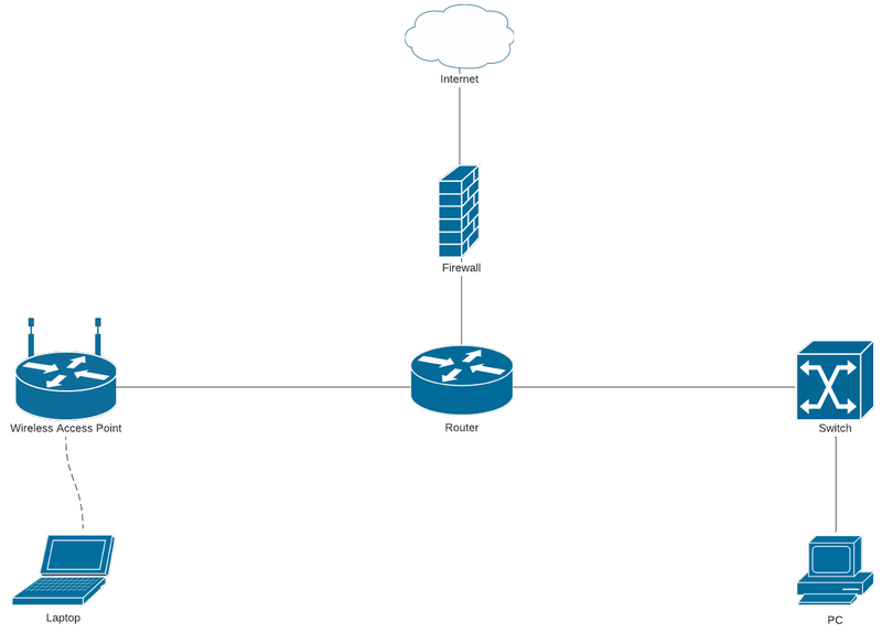 Mapping A Network Diagram A Step By Step Guide The Blueprint
 Visio Stencils Basic Network Diagram Techbast
 Pin Op Architecture Design Patterns
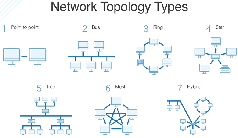 Mapping A Network Diagram A Step By Step Guide The Blueprint
 Computer Network Diagram Wikiwand
 Ethernet Network Ethernet Local Area Network Layout Floor Plan Network Layout Floor Plans Ethernet Network
